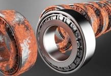
A new version of the MESYS shaft and rolling bearing analysis software including new functionality is available. The bearing analysis software allows the calculation of the load distribution within the bearing and bearing life according to ISO/TS 16281 and it is integrated in a shaft system calculation with additional possibilities like modal analysis, strength calculation for shafts and interfaces to gear calculations. Currently the software is used by customers in 31 countries on 4 continents. The new version is now available under Downloads.
General Extensions
The bearing databases from Barden/HQW and SKF are updated and a new database from NSK is added. The encrypted Barden/HQW database contains the internal geometry while the SKF and NSK databases only contain catalog data.
Custom diagrams can now be defined based on the input in the parameter variation. They can be added to the graphics menu or the main report. Application related diagrams can be defined easily and saved with the calculation file.

The software was available in both a 32bit and a 64bit version for now 12 years. Now the 32bit version is not supported any more and only a 64bit version is available.
Extensions in the Bearing Calculation
The X/Y-factors for the life calculation according to ISO 281 can optionally be calculated from the free contact angle instead of the nominal contact angle. This allows to consider bearing clearance especially for deep groove ball bearings in life according to ISO 281.
 For the calculation with elastic surroundings now the gap width to the housing can be specified in addition to ring deformations. This allows to differentiate between a cylindrical bearing ring in a non-cylindrical housing and a non-cylindrical bearing ring in a cylindrical housing. Of course, both parts can have roundness deviations in one calculation too.
Deformations of bearing rings can now be shown as animation.
Extensions in the Shaft Calculation
In the shaft calculation 3D-deformation views are available as animation now. Several options are available to configure 3D-views like enabling or disabling some components like coordinate system or housings.
The extended bearing model now allows to consider spacers between two bearings directly now, without adding a part for the spacer. These spacers then have the same temperature and material as the right bearing. For standard cases the definition of spacers will be faster now.
The possibilities for CAD-exports have been extended and a preview was added. First a 3D-graphic is shown from which the STEP export can be done. For cylindrical gears and bearings also a detailed geometry is available showing teeth and rolling elements.
For 3D-elastic parts orthotropic material data is supported. Now this material information for orthotropic materials can be added into the database. The import of 3D-geometry now also supports closed sheet bodies in addition to solids.
Extensions in the calculation of Axial-Radial-Roller-Bearings
The calculation module for axial-radial-roller-bearings now also includes a parameter variation like the other calculation modules. This allows to vary geometry data and for example the stiffness can be shown over bearing clearance.
 Stiffness values can now be calculated directly for one or more reference points without using several load steps in the series calculation.
New calculation module for cylindrical gear pairs
As new module a calculation for cylindrical gear pairs is added. It can be used as standalone program or integrated into the shaft calculation.
 The cylindrical gear pair calculation supports following features:
- Gear geometry calculation according to ISO 21771-1. For internal gears all input and output diameters are used as positive values in the software as they are used for manufacturing and documentation. Only the number of teeth for internal gears is set to a negative value.
- Gear strength calculation according to ISO 6336 parts 1, 2, 3, 5, 6. Different options are available for the tooth thickness and contact ratio to be used.
- Support for load spectra. In addition to speed and torque also mesh deviations, face load coefficients or mean stress influence factors can be defined in the load spectrum.
- Parameter variation to vary geometry or loading with output in tables and diagrams
- Tooth form graphics for single teeth, full gear, manufacturing or engagement
- Graphics for specific sliding, safeties over life, permissible torque over life
- FEA based tooth form stress using 2D-FEA. For helical gears either the virtual spur gear can be used or the normal section.
- 3D-Gear geometry available as STEP export. The transverse section is generated with a accuracy better than 10-4*mn*cos(β) and then extruded along a helix. Accuracy along the helix depends on the CAD system. Currently no profile or flank modifications are included.
The eight calculation examples from ISO/TR 6336-30 are included in the installation.


